This week, let’s get to know the next type of Stakeholder requirement – State Transition diagram. Recall from previous posts, State Transition diagram shows change in all possible states of an entity. It belongs to Data and Information modelling category, and is drawn using State Modelling technique. Following UML standard, State Transition diagram is also known as State Machine Diagrams.
Firstly, let’s take a look on the below sample of State Transition diagram:
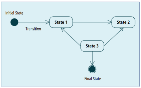
(IIBA. 2015. BABOK. [Image])
It depicts all required elements of a State Transition diagram:
- Initial State and Final State. They are not state but considered as “special state”, thus they are also known as pseudostate (pretended-state) in UML. They are indicated by special symbols and vary for each standard or notation. The image above shows Initial State and Final State following UML standard.
- State: a State Transition diagram must list all possible states of the entity in the system. Each state is shown in a rectangle with rounded corner.
- State Transition: the transition is implied with the direction flow (one-directional arrows) and trigger (the action which causes the change in state). While the direction flow is required, the trigger is optional in this diagram.
The trigger label comes in 3 parts: trigger-signature [guard]/activity. The trigger label itself is optional, thus all 3 parts are optional. The trigger-signature is usually an event that triggers the change in state. The guard is a boolean condition that must be true for the transition to be taken. The activity is behaviour which is executed. Normally, I use trigger-signature in the State Transition diagram and skip the other two. There is no standard format for this trigger-signature, but I normally use Actor: Action. Of course, it’s just the habit, not any standard to follow.
Every state must have at least 1 coming arrow and 1 outgoing arrow, but there might be more than 1. On the other hand, there must be at least 1 way for the entity to reach that state and at least 1 way to get out of that state. However, the sequence of states is not linear, an entity can skip some states or revert to the previous state, as you can see in another example below:
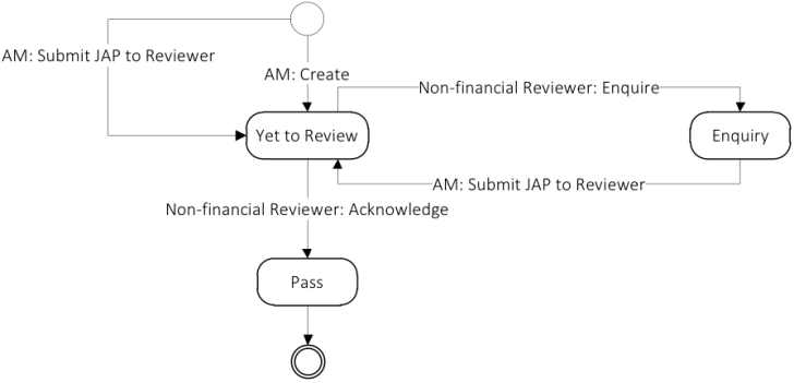
In this exhibit, the entity might change from Yet to Review state to Enquiry state in case Non-financial Reviewer enquires the item. It also can revert from Enquiry state to Yet to Review state in case AM re-submits the item for review.
Or in the sample below, the entity might skip Converted to Opportunity state to change from New state to Completed state.
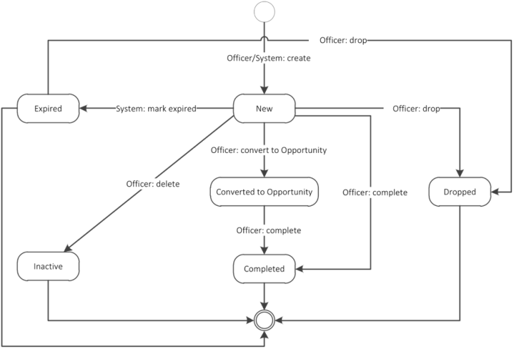
The transition might be conditional (triggered by a special event or a condition being reach, or you can see Officer: delete in the exhibit above) or automatic (triggered by the completion of required activity or by the passage of time – or you can see System: mark expired when entity state change from New to Expired in the sample).
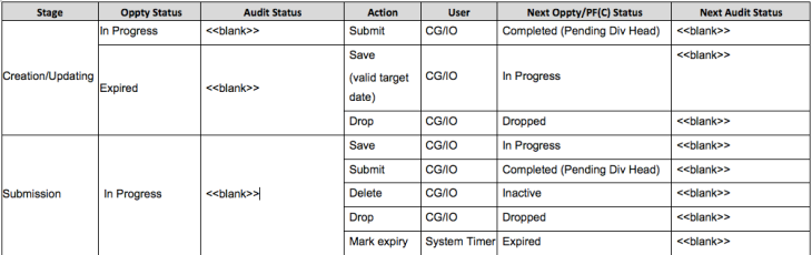
- State Tables: this table is two-dimensional matrix showing states and transition between them, with each row showing starting state, transition event and the end state. Normally, this table is used to elicit requirement and used as an alternative for the state diagram, as it offer the advantage of easier modifying. However, for complicated entity, this table can be added below the State Transition diagram to entails the state transition. You can see an example of state table as below:
Thanks for reading 🙂
Reference:
- IIBA. 2015. BABOK. Version 3.0.
- Martin Fowler. 2003. UML Distilled. 3rd ed.
